6 -Axis Robotic Arm

Design Goals
The design goals for this project were to design, fabricate, and build a 6-axis robotic arm within the span of a single summer. Specifically, I wanted it to have a 500mm (half-meter) reach with a payload capacity of 4 pounds. I also wanted to use absolute magnetic encoders on each joint to detect skipped steps, avoid complex homing routines, and make calibration easier.

Frame
The frame is made of 1 inch aluminum extrusions. I made sure to use ¼ inch 6061 aluminum brackets on the frame corners to hold it together. The plywood base is used to hold all of the electronics that can’t fit in the service box, and a ¼ inch 304 steel plate is used to mount the base components of the arm. I also added some simple rubber furniture feet to add some height to the frame.


Electronics
The electronics start from the main 24V power supply, which feeds into the stepper drivers and a 24V to 5V buck converter. The first two joints are powered by Nema 23 stepper motors using DM542T industrial drivers, while the remaining joints use Nema 17, 14, and 11 motors paired with the more compact DM320T drivers.
I chose to use a centralized 24V power rail instead of 12V to combat the back-EMF and electrical noise generated by the larger Nema 23 motors. The shoulder motor in particular sees the highest forces and is rated for 2.8 Amps. Using this larger motor meant I didn’t have to create as large of a gear reduction, which would have sacrificed efficiency. There is also a hardware E-stop wired directly to each of the drivers to instantly stop all motor power.
The main challenge I faced when designing the electrical architecture was bridging the logic voltage gap between the industrial stepper drivers (5V logic) and the magnetic encoders (3.3V logic). I chose the Raspberry Pi Pico because of its pin count, programming options, and programmable I/O state machines, which allowed me to quickly read and process encoder data without stressing the main cores.
To solve the logic voltage difference, I utilized a Push-Pull signal architecture with the drivers wired in a Common Cathode configuration (meaning the PUL and DIR terminals share a ground pin). Rather than relying on simple pull up resistors which would slowly charge to the circuit’s total parasitic capacitance, the Pico actively pushes current (sourcing 3.3V) into the driver’s optocoupler LED, and then actively pulls the circuit to ground (sinking it). This method uses the Pico’s internal P and N channel mosfets. When a pin is not sending a HIGH signal, it switches to ground which ensures the square waves are clean and can switch at high frequencies.


Base Turntable
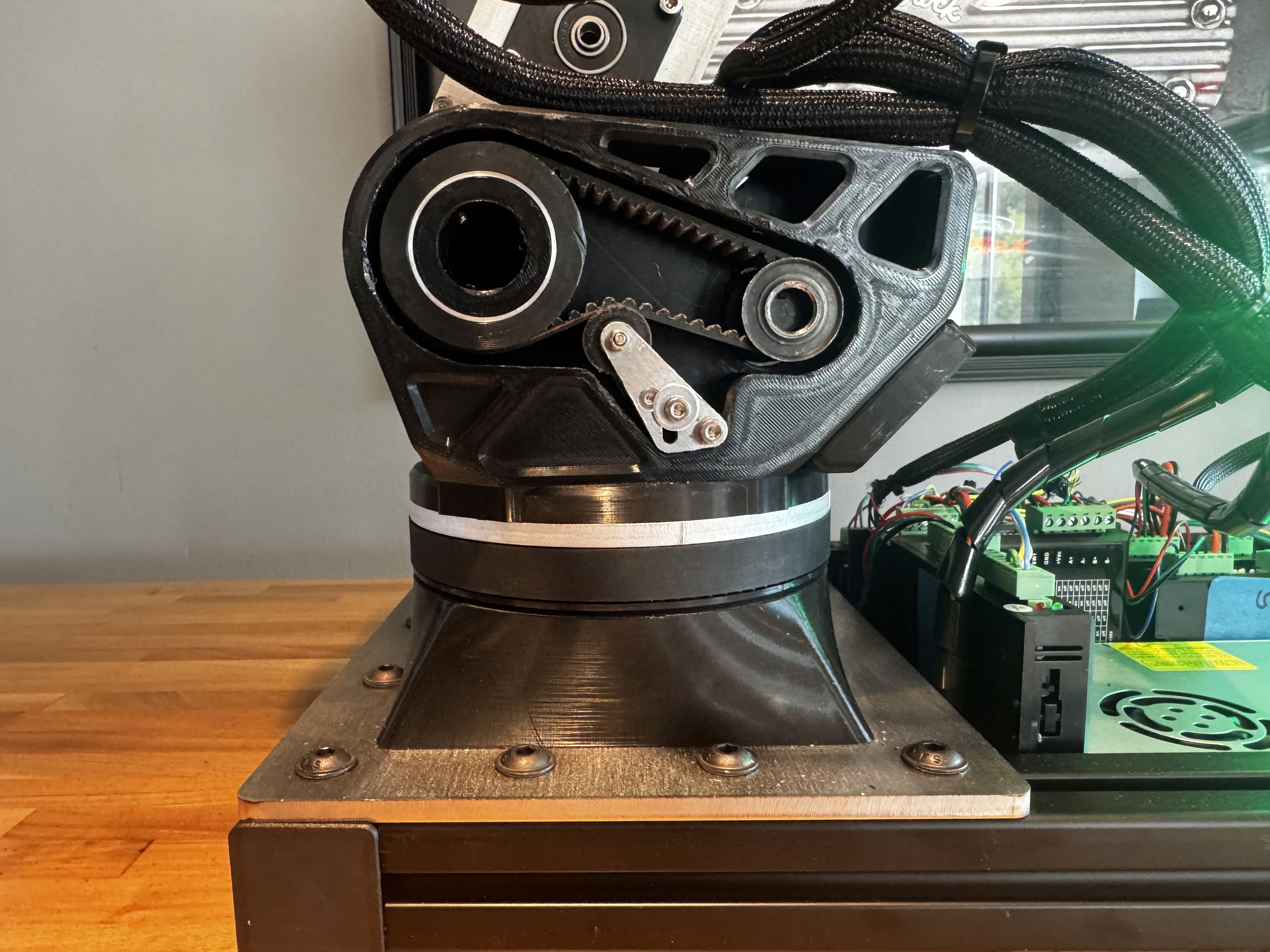
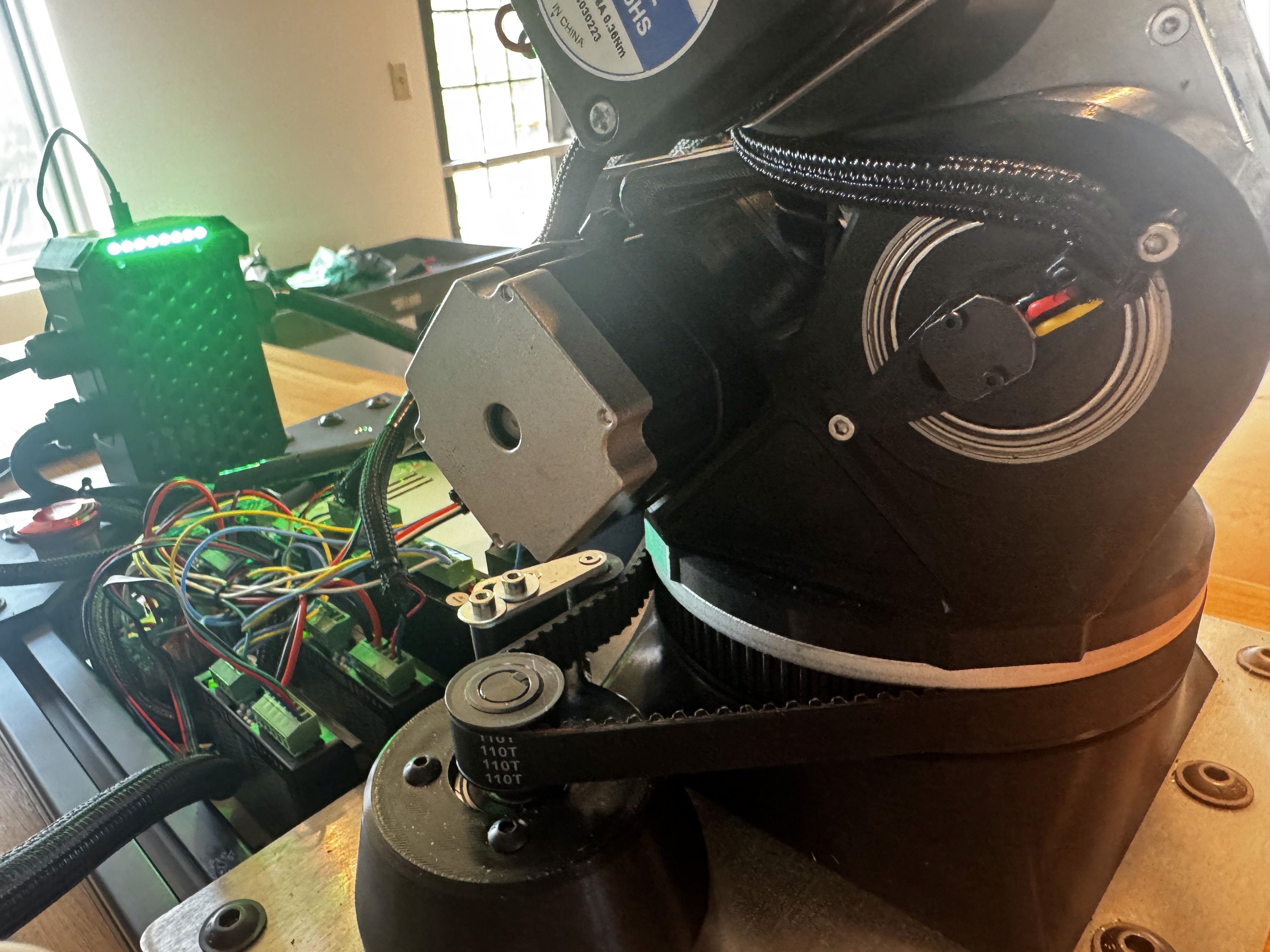
The turntable, which is attached to the ¼ inch steel plate, is made of two parts: the motor mount and the turntable holder. The motor mount allows the Nema 23 and its 4:1 gearbox to be recessed into the lower frame, keeping the base low to avoid excessive stack height for the overall arm.
The base incorporates the first magnetic encoder and a crossed roller bearing, which acts as the backbone of the arm. Crossed roller bearings are the industry standard for robotic arm applications because they have very little play, can be loaded both axially and radially, and are easy to mount components to with two circular hole patterns. Above the crossed roller bearing is a ¼ inch aluminum mounting plate that sandwiches the bearing and the plastic shoulder plate. This stack height adds enough clearance to add a 15mm HTD belt pulley, increasing the mechanical advantage of the turntable even further.


Shoulder + Linkage 1
The shoulder and first arm use thick 3D printed plastic to constrain the motor and arm components. I used a 15mm HTD belt here for a few key reasons. First, the belt drive allowed me to flip the motor 180 degrees, keeping the packaging much cleaner and shifting the moving mass closer to the center. Second, the belt has very little backlash, meaning the only real backlash in the system comes from the 15:1 planetary gearbox before the belt stage. I chose this specific method because these belts are rated for huge loads, and I knew that during initial testing, I could intentionally loosen the belts to slip and prevent crash failures.
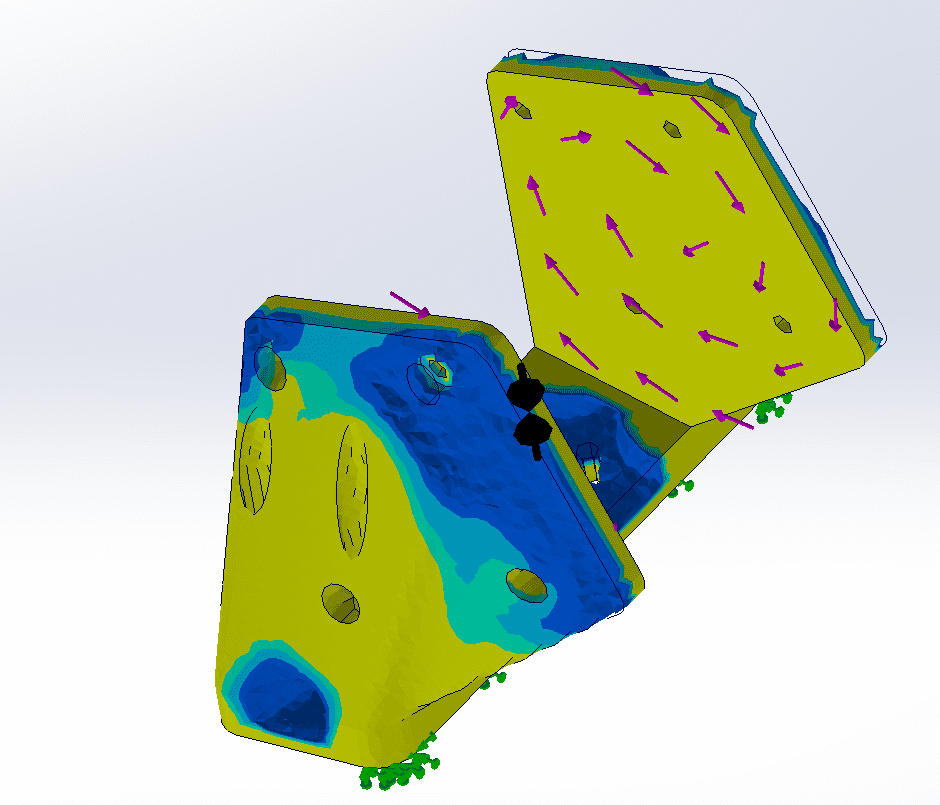
In other joints, I continued using belts to push the heavy motor mass away from the ends, which reduces the moment of inertia. Additionally, I put some time into simulating and testing the aluminum arm’s weight saving patterns to keep parts light and as strong as they need to be.



Elbow + Wrist 1
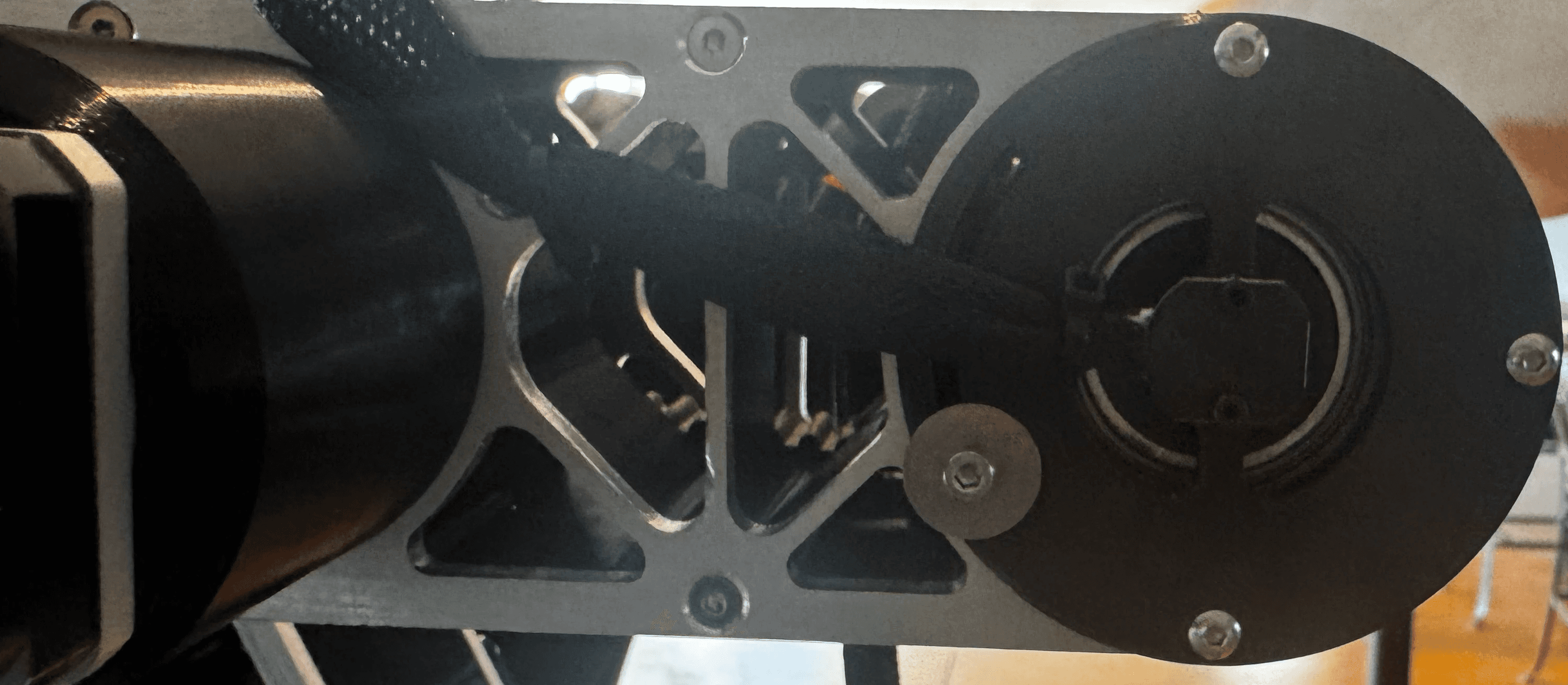
The Elbow uses a Nema 17 with a 50:1 planetary ratio and an HTD belt to shift the heavy motor and gearbox away from the tip where the wrist and future tools will be actuated. For the forearm twist, I set up a large reduction driven by a Nema 11 motor to rotate the entire second linkage. There is a hidden magnetic encoder located at the start of the second arm that reads the exact absolute angle of this Nema 11 wrist twist. The second arm is perfectly balanced, meaning the torque forces on the wrist twist only become substantial when the arm is actively moving an external payload.

Wrist 2
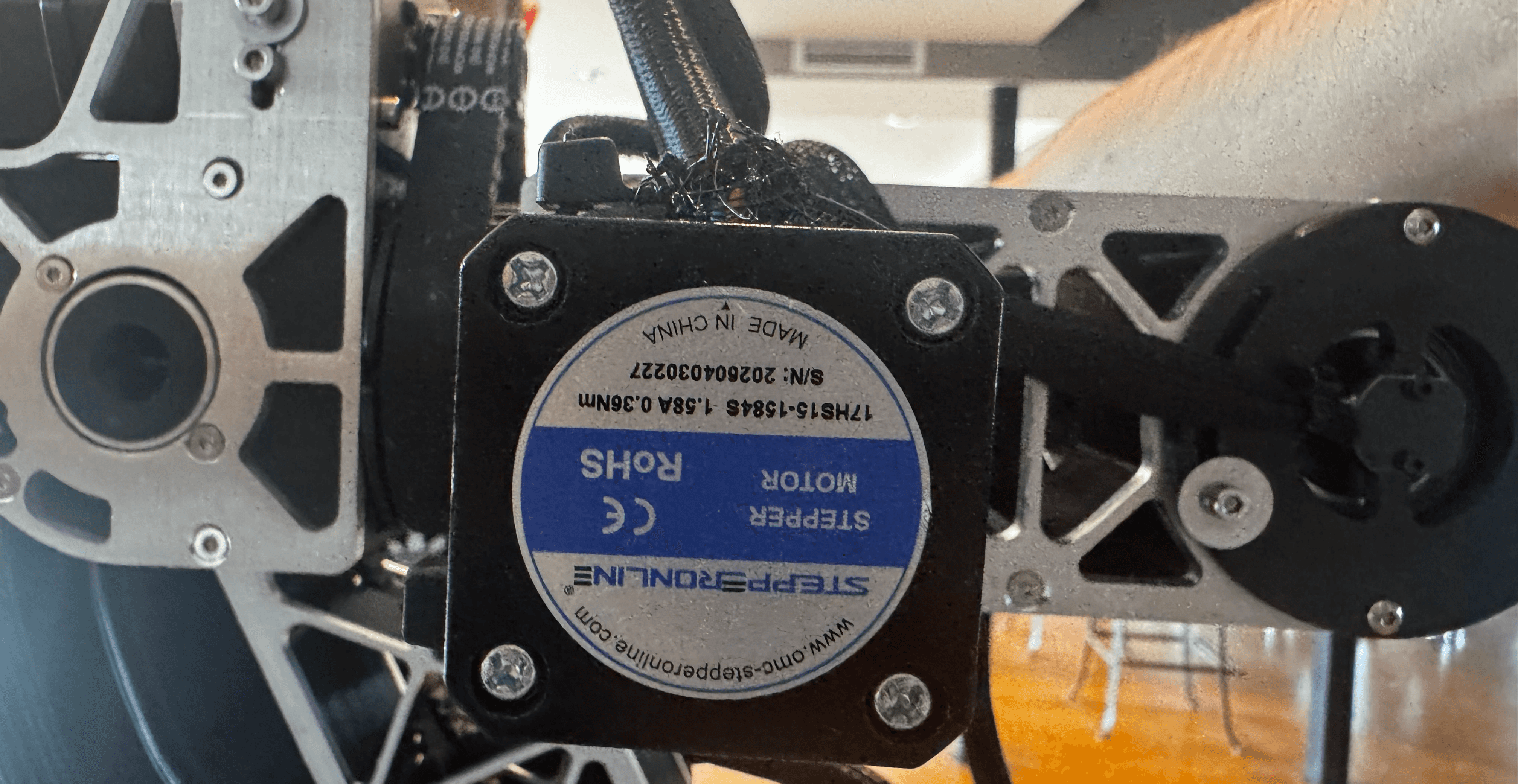
The second wrist joint uses the same Nema 17 as the elbow joint. However, this one uses a slightly smaller gear reduction because it is moving significantly less mass further out on the arm. The second linkage it attaches to also uses the same encoder setup as the first linkage, which can be seen in the photos below. Just like the first linkage, I have hidden the belt inside the arm profile to allow for cleaner packaging.


Wrist 3
The final wrist joint (which provides the 6th degree of freedom) is directly driven by a Nema 14 and features a magnetic encoder positioned before the gear reduction. Ideally, I would want this encoder on the final output shaft of the gearbox to read the true tool position, but due to time and packaging constraints, mounting it on the motor shaft was the best physical option. The only downside here is losing true absolute positioning across multiple rotations, requiring occasional homing, but I am currently developing a solution that will eliminate the need to home this joint entirely.




Previous Designs and Prototypes
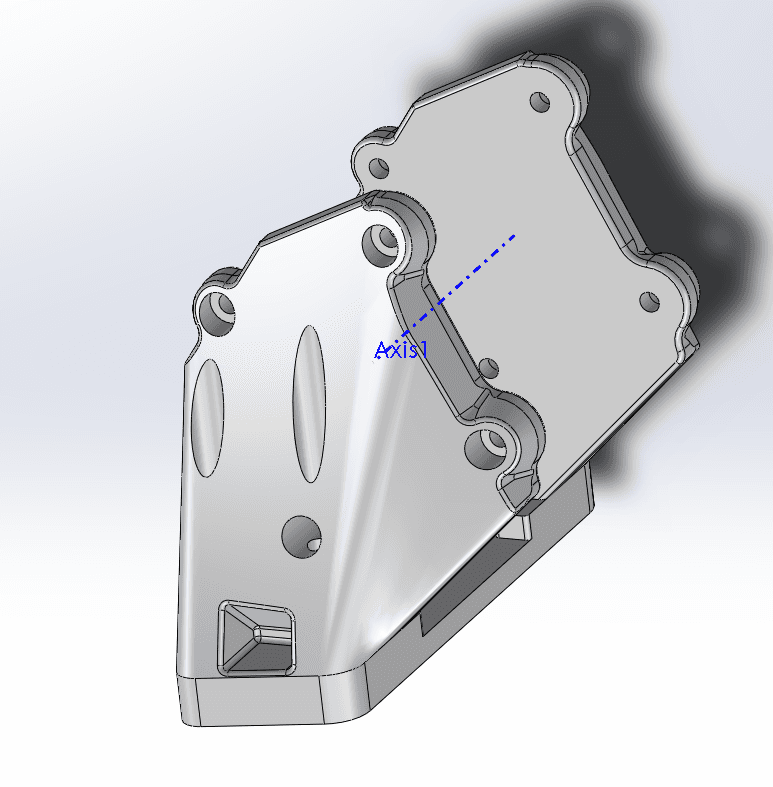
Above, you can see some previous scrapped designs. There are Wrist 3 prototypes where I explored getting the encoder to read the true output position. There are also previous shoulder joint designs where I considered using bevel gears instead of the HTD belt where the motor hung off the back edge to physically counterbalance the arm. I also considered a design using hollow circular tubes, where the Nema 17s and bevel gears would be completely contained inside the hollow cavity.
Common Design Questions
Why so many belts: High torque, low backlash, remote motor mounting, vibration isolation, can easily change tension
Why is magnetic encoder absolute position so important: Having the encoders on the output of each joint lets me see the position without needing to ever home, this also allowed me to create custom backlash and gear ratio tools so I would have the joint move and the encoder would read that movement to run some math which gives me the exact gear ratio and the backlash values which can be compensated for in software
Why so many printed parts: I am very comfortable with printed parts in these kinds of projects, I used metal parts where needed for structural components that can’t be too bulky and I use plastic parts where needed where I can bump up the infill numbers and extend the geometry a bit to give it more strength. I used lots of brass inserts to couple the components together which give a very strong screwable connection between plastic parts. Using lots of printed parts also keeps the weight and cost down while letting me iterate on parts in a short time frame.